 WEBSITE
UNDER CONSTRUCTION WEBSITE
UNDER CONSTRUCTIONPHOTOGRAPHS AN 1880 COMMERCIAL MODEL SLOOP USED IN THE SAN FRANCISCO BAY AREA THE MAGIC SLOOP Viewer
Note: If
anyone reading website has seen any
documentation on this kind sloop or documentation on the
doghole schooners, please
contact me or the Maritime Museum. By documentation I mean
ANY letters describing this kind of sloop or documentation
on doghole schooners. We are all looking for photos,
drawings, or description, of 1850 to 1920 sloops or and
doghole schooners. We would be interested in models of
any kind - half/full etc. I am very much afraid both the
sloop and the doghole schooner are very close to total
extinction.
The only tool left to find this information is the internet, 100 years into the future from this documentation - oddly enough. The reality is that there probably is a little paper information still around in old attics, boxes, or old buildings inherited boxes, etc. But we are losing the information day by day...to time. Once the information is lost it is gone forever...there is no backup disk - it can not come back and it can not be retrieved. This sloop is the truck of the 1880s. Imagine losing all the documentation (all photos, drawings, written text, models, etc.) of the Henry Ford model "T". Or in the sailing world, imagine all information on the Bluenose was lost! 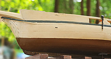 This
page
here to share the details of the model donated to the San
Francisco Maritime Museum. This model was featured in the
museum's periodical called "Sea
Letter". This periodical is sent out to members
quarterly. The photography in the "Sea
Letter" is so well done I have copied the style on this
website. GREAT photography Cris White - thank you. This
page
here to share the details of the model donated to the San
Francisco Maritime Museum. This model was featured in the
museum's periodical called "Sea
Letter". This periodical is sent out to members
quarterly. The photography in the "Sea
Letter" is so well done I have copied the style on this
website. GREAT photography Cris White - thank you.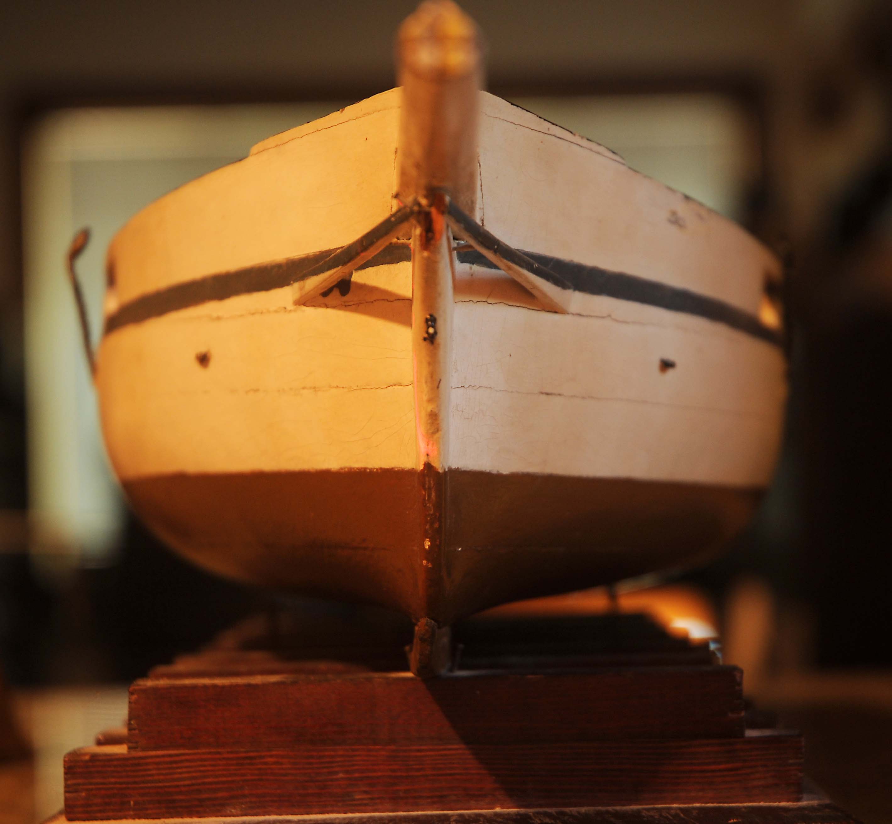  Bow detail shows slab construction of the model and rails to strengthen the bow construction. The bowsprit is eight sided. 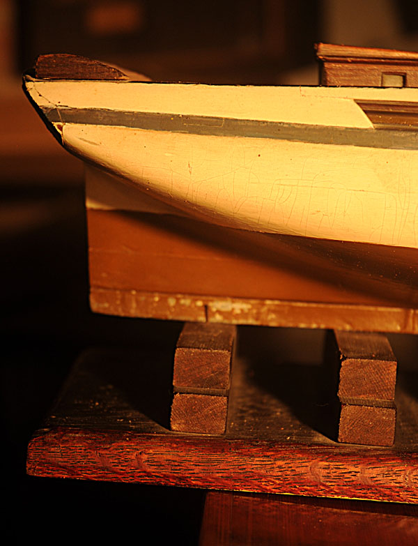 Transom Side View
What
I
found, with a lot of study of this view and others, that
the very smooth curve of the hull at the water line is
critical for speed. After some thought and some guessing I
suspect this fast smooth hull reduced turbulence
("friction"), and allows the transom to be safely above
the water line. These sloops were quite fast, had an
extremely shallow draft, and could be sailed up or
down a river and often against the wind.
 The base holding the model in this photo is the original builders base with no changes to the base. I
suspect the added transom, which shows as a broken line,
was added to produce a flat transom on the
model. I suspect this because I had the same problem
with that transom cut is about 15 degrees and extremely
difficult to maintain.
Each time a person shapes the hull that last transom area gets smaller and shorter from hull shaping. I finally had to add a 1/8" thick sheet of wood to the transom to return to my matching length. I then had the right length and a perfect flat surface on which to paint a name. I then looked at the model and realized I had made the same mistake the original model maker made 148 years ago!
No
changes have been made to the model or the base - every
detail is original to the original build.
This model is just as the model maker left it in
approximately1880.
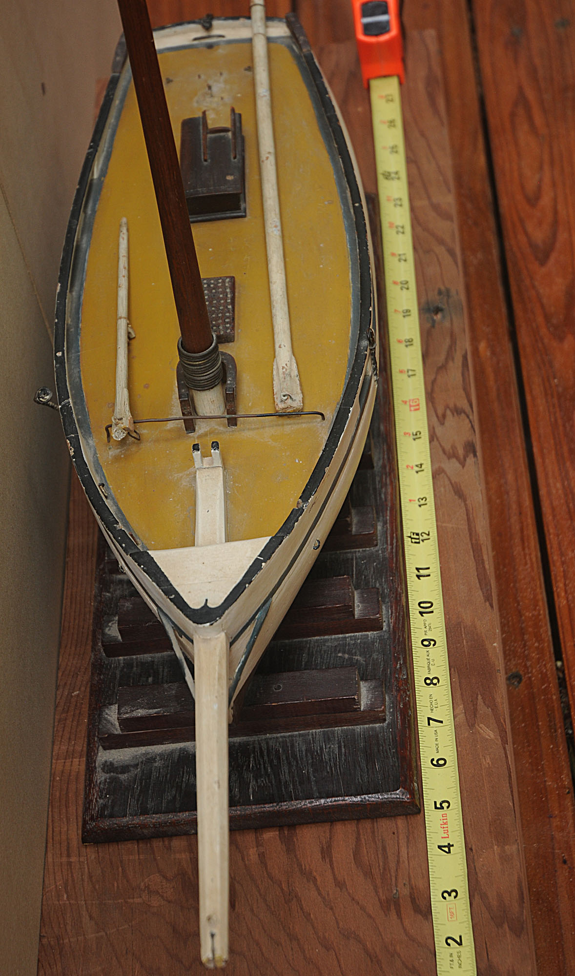 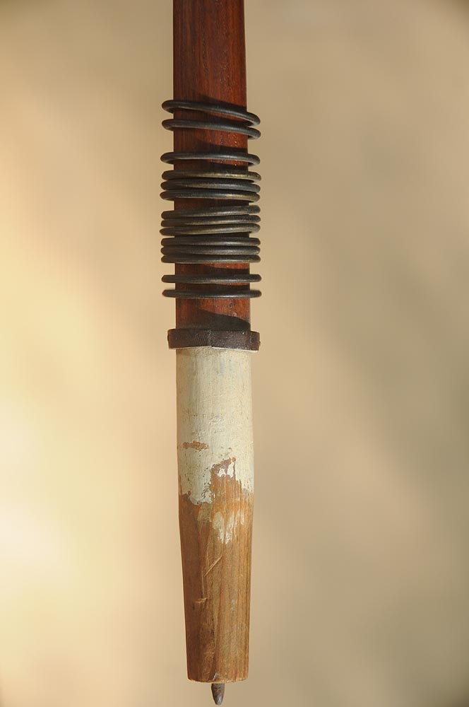 Above: This is a very detailed view of the bottom of the single mast. I tried to duplicate this mast on a wood lathe and every time I made a new version - a copy - of this mast, I always made the copy too thin. The point is that this mast is much heavier and thicker (stronger) on on the real boat than I would have imagined. The brass point at the bottom fits a hole inside the model and always assures the proper vertical alignment. Above Right: This view is from the bow and also shows two parts of the rigging the boom which is exactly as long as the mast is high and the gaff is to the left. The lengths of the model and boom is are about 20 inches. The beam is about 1/3 the length or about 7 inches. This is the hull with a laser line to show the true shape of the hull. The laser is a simple carpenter spot/line laser from Home depot. I made a copy of positions every half inch down the hull. This has enabled me to produce a very accurate cross section at points every half inch along the hull. I know there is a slight error and that allows me to see the line to the maximum beam curve. I used a Photoshop image and measured the alignment error and it was purely horizontal. I also measured with Photoshop what the error would do to the cross section and the result is about a 1 mm error and that dimension works out to be the half the thickness of a plank. Laser line hull shape approaching bow with 1/2" steps Using Photoshop I can strip the red laser trace from the laser on the hull and make a simple half-profile from the laser line. I can then flip one image horizontally and show both on a drawing with the keel added. From this process I can make a full set of templates from the original model without harming the original model or paint. Imagine showing this simple carpenter laser image to the maker. 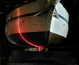 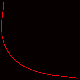 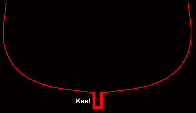 The laser lines you see to the right of the model each come from the model with laser line on it. The isolated lines in the center and on the right have been stripped and manipulated from the left side model with laser line image using Photoshop. 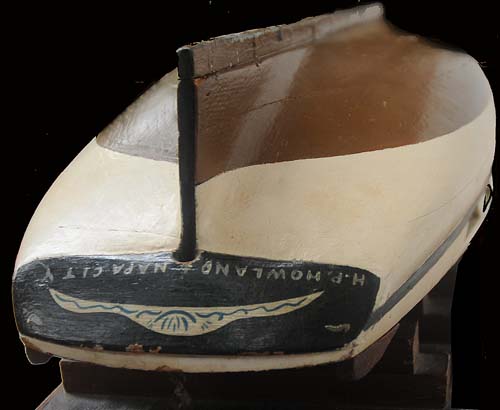 Inverted Views Now that I have examined the detail of some fill between the hull and the keel near the transom over the wood work. I do believe the fill is a kind of planking putty because I could see very slight finger marks in the putty - putty does not sand or smooth well when it is soft but it is well cured now, 148 years later. I know because I had exactly the same issues when I made my model of the model - especially around the transom. You can still see, looking very carefully, and noticing the sanding marks in the dark paint - it was and is a very difficult area to smooth, full of intricate curves and transom joints and edges! 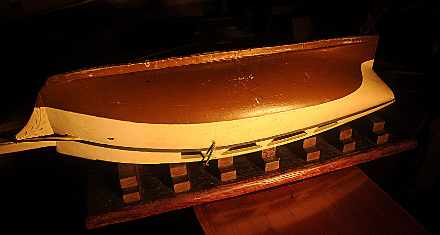 Side inverted detail to show hull to keel information Note the continuous curve of the hull from transom to bowsprit. This curve of the hull in this photo is part of the reason these were very fast sloops. 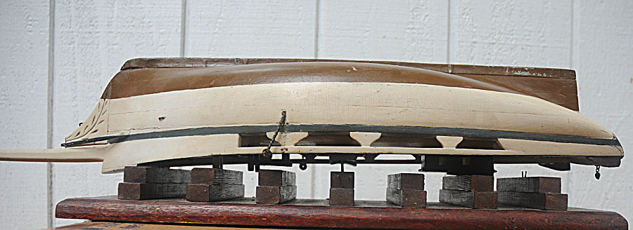 Transom Lettering Detail Boom and Gaff Rigging Pieces Please remember I am about as green as it gets with this kind knowledge of detail! An observation I made photographing the rigging detail. Although you can not see the tied lines, there are places where the lines are twisted but tied by a second piece of thread, with a different knot, probably to match the real rigging as much as possible. And the bone or ivory pulleys, in particular, show what looks like wear marks on the pulleys where the wear should be on a well worn pulley. Some of this shows on the lower image here. Each pulley on the model is hand made. The history curator at the Maritime Museum made the comment looking at the spars - "well at least someone knows how to make model spars". Take a minute and look at these rigging pieces and forget that it is a model. They look like the real rigging! This a goal of every model maker - to make something that seems real to a viewer if the viewer can momentarily adapt to the size of the model. 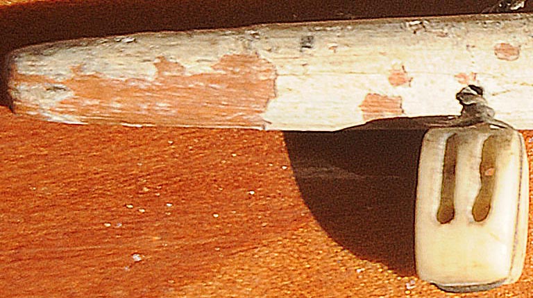 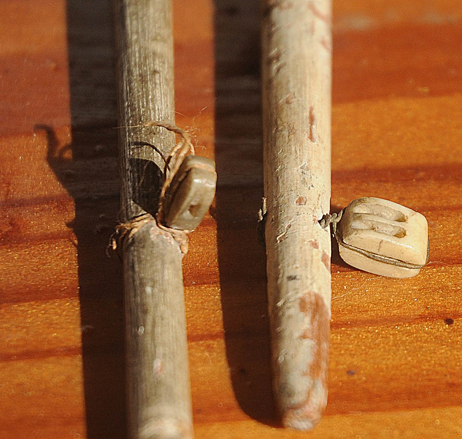 |